
Structural Design of Riding Crawler Rotary Tiller
Core Module Analysis for Structural Design of Riding Crawler Rotary Tiller
Crawler Travel Chassis Assembly
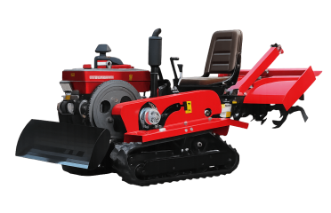
The crawler chassis lays the foundation for the whole Riding Crawler Rotary Tiller. This assembly includes driving sprockets, idler wheels, supporting rollers, track frames and heavy‑duty rubber or steel crawler belts. Unlike wheeled farm machinery, the wide contact surface of crawlers distributes total machine weight, which effectively lowers ground‑contact pressure. This key feature enables the Riding Crawler Rotary Tiller to travel across water‑saturated paddy soil and soft orchard ground without sinking.
Within the overall Structural Design, reinforced welded steel track frames resist continuous vibration generated during high‑intensity rotary tillage. Many premium‑grade models adopt adjustable track tensioning mechanisms; field operators can manually fine‑tune crawler tightness on‑site, reducing track‑slippage or derailment risks when working on sloped farmland. The chassis ground‑clearance value directly determines the machine’s passing capability over crop stubble, and it is a critical technical parameter that overseas dealers always verify before placing bulk orders. Typical working specifications for mainstream commercial versions range from 18 cm to 32 cm ground clearance, with working width varying between 1100 mm and 1600 mm according to different configurations.
Power & Transmission Assembly
The power module is embedded at the middle‑front section of the frame in most mature Structural Design solutions for the Riding Crawler Rotary Tiller. A water‑cooled diesel engine provides primary power output. Power is split by the transfer gearbox: one power flow drives the crawler travelling system, the second flow transmits torque to the rear rotary tiller shaft for soil‑breaking operations.
Reasonable power split design is essential to prevent power conflict between travelling movement and rotary cultivation. If the transmission gearbox is under‑reinforced, users will encounter stalling or gear‑damage issues when tilling heavy clay soil. Premium‑spec machines use alloy steel gears inside the gearbox, with sealed lubrication chambers to keep mud and field dust out, extending service life under harsh farm‑site working environments.
Operating Control System
The operating control system forms the human‑machine interaction core of the Riding Crawler Rotary Tiller. This subsystem consists of operator seat, multi‑function control levers, instrument dashboard, hydraulic lifting valve group and emergency‑stop safety mechanism. Under good Structural Design, all main operating levers are arranged within convenient arm‑reach range of the seated driver. The instrument panel displays real‑time engine water temperature, rotational speed and fuel level so that operators can quickly spot abnormal working status.
Hydraulic control circuits manage the lifting and lowering of the rear rotary tillage implement. With one‑lever operation, the driver adjusts tilling working depth flexibly while moving across different soil zones. Modern‑era improvements to the operating control system also include shock‑absorbing driver seats to mitigate whole‑machine vibration during long‑hour continuous field work. Safety‑focused structural upgrades integrate mechanical emergency‑stop function: cutting power immediately once abnormal situations occur to protect the field operator.
Rear Rotary Working Assembly
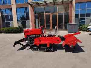
The rear working assembly includes heavy‑duty rotary cutter shaft, manganese‑steel tiller blades, anti‑winding guard cover and connection suspension bracket. The arrangement density, bending angle and material hardness of rotary blades directly affect soil‑crushing quality. In well‑optimised Structural Design, the protective cover above the blade set prevents tangled straw and crop residues from winding around the rotary shaft, reducing downtime for manual cleaning. The suspension bracket connects the working unit with the main chassis frame via hydraulic cylinders, making depth adjustment responsive and stable.
Manufacturing Process & Quality Control for Key Structures
The manufacturing workflow for the Riding Crawler Rotary Tiller starts with laser cutting of steel plates for chassis frames, followed by robotic welding for high‑stress joint points. Weld seam inspection is an indispensable quality‑control checkpoint; weak welding points on track frames or suspension brackets are the most common failure sources reported by end‑users overseas.
After frame fabrication, the factory proceeds to assemble the engine, transmission gearbox, operating control system, crawler components and rotary tillage assembly sequentially. Final‑stage running‑in testing is conducted on simulated farm ground inside the workshop. Machines will complete continuous no‑load and loaded running tests before paint‑spraying and packaging for export shipment. Reliable manufacturers implement batch sampling inspections on critical spare parts such as gears, crawler belts and tiller blades, to guarantee consistent quality for each shipment.
International Buyers’ Pain Points & Procurement Preferences
Many overseas distributors and farm operators have shared practical pain points related to the Structural Design of the Riding Crawler Rotary Tiller. The most frequent complaints focus on insufficient chassis rigidity, poor anti‑dust sealing for transmission boxes, and inconvenient maintenance access around the operating control system. Many low‑cost export models cut material thickness on the frame, which leads to frame deformation after one or two busy farming seasons.
Currently, professional international purchasers are no longer only comparing horsepower and selling price. When evaluating a Riding Crawler Rotary Tiller, they first inspect the overall Structural Design: checking frame‑plate thickness, gear material grade, accessibility of maintenance points, the ergonomic layout of the operating control system, and the anti‑winding structure on rotary working assembly.
Buyers for hilly‑terrain markets prioritize reinforced crawler chassis and stable slope‑operation performance. Customers for orchard farming prefer compact overall width, while paddy‑region purchasers focus on low ground‑pressure crawler configuration to avoid sinking. For bulk procurement projects, experienced importers often require factory‑supplied structural drawings and key component test reports, before confirming formal purchase contracts.
FAQ
Q1: Which part of riding crawler rotary tiller is most easily damaged in field operations?
A: Under heavy‑load farming conditions, rotary tiller blades and crawler components suffer the highest wear rate. Nevertheless, unreasonable overall structural design may also cause early‑stage fracture of the main chassis frame.
Q2: What improvement does the upgraded operating control system bring for riding crawler rotary tiller?
A: Optimized operating control system delivers simpler depth adjustment, clearer real‑time working data on dashboard, vibration reduction for the driver, plus reliable emergency‑stop safety protection.
Q3: Is structural design different between paddy‑field version and orchard version of riding crawler rotary tiller?
A: Yes. The orchard‑special model adopts narrower overall chassis width for passing between tree rows. The paddy‑field variant focuses on low ground‑pressure crawler belts to reduce sinking risk on wet mud soil.
Q4: Can end‑users replace rotary blades and crawler belts by themselves?
A: Standard spare‑part design allows on‑site replacement. It is recommended that buyers source original spare parts from the manufacturer to keep the whole structural performance of the riding crawler rotary tiller stable.
Conclusion
The Structural Design of the Riding Crawler Rotary Tiller determines machine durability, field adaptability and operator‑friendliness across the whole product lifecycle. The crawler chassis, power transmission, operating control system, and rear rotary working assembly are four inseparable core modules. As global small‑farm mechanisation keeps advancing, continuous optimisation on mechanical structures will further expand the applicable scenarios of this specialised farm machine. For distributors, cooperative farms and rental‑service businesses, selecting a unit with mature, well‑engineered structural layout can effectively lower long‑term repair cost and improve return‑on‑investment.